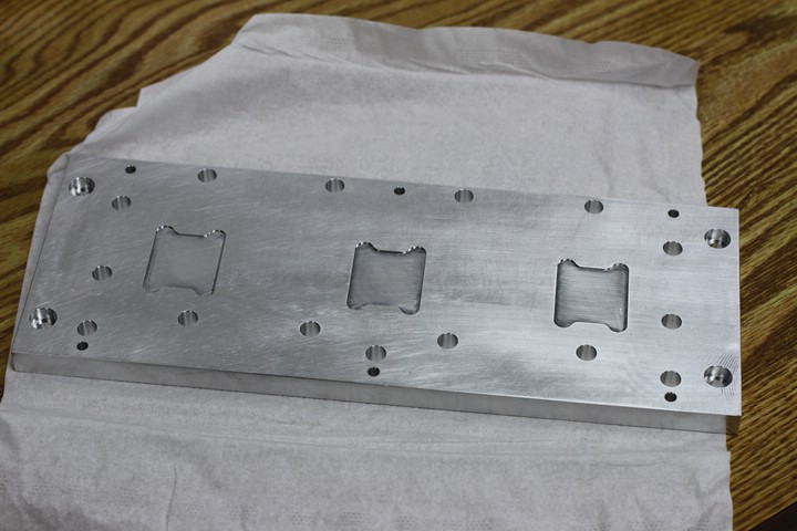
Base for the long cavity laser.
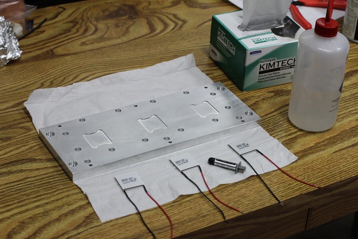
Printed text on the TECs faces up.
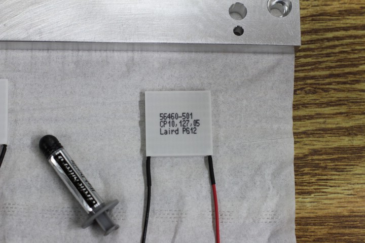
TEC and Artic Silver thermal paste.
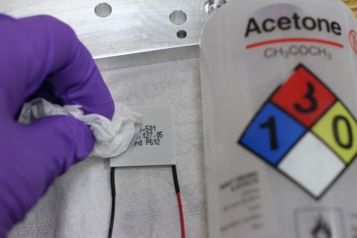
Cleaning the TEC. This isn't really necessary.
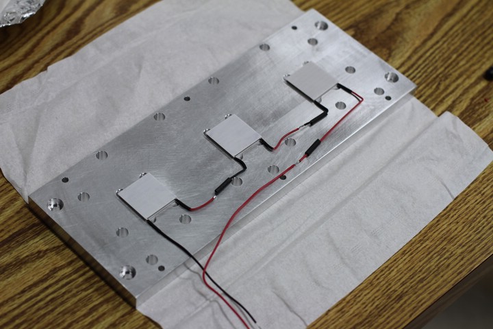
TECs wired in series. The text has been cleaned off, but the proper side is still facing up.
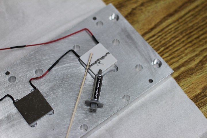
Very little thermal paste is necessary. Make it as thin as possible without showing any of the TEC surface.
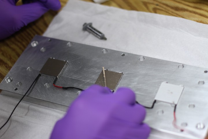
Using an applicator stick to get an even layer.
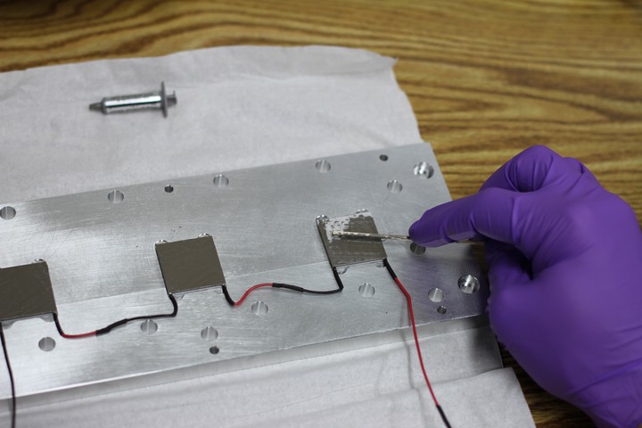
More thermal paste.
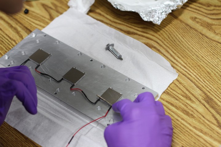
Remember to apply thermal paste to both sides of the TEC.
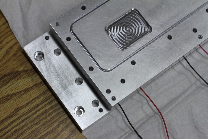
When placing the bottom cover on the base, ensure that the access holes in the base line up with the screw clearance holes in the bottom cover.
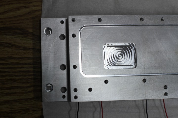
Line 'em up.
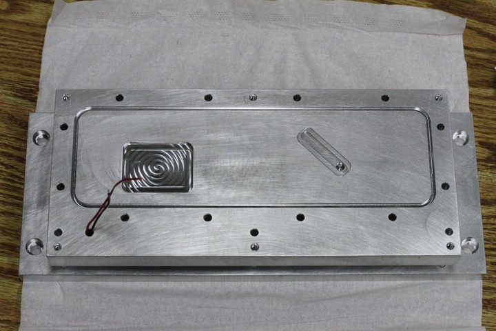
The TEC wires must pass through a small hole in the bottom cover.
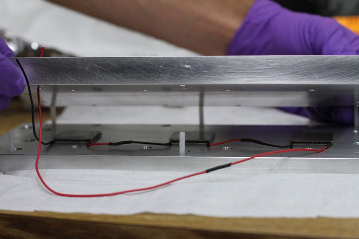
Nylon screws are used to secure the base to the bottom cover to ensure thermal isolation.
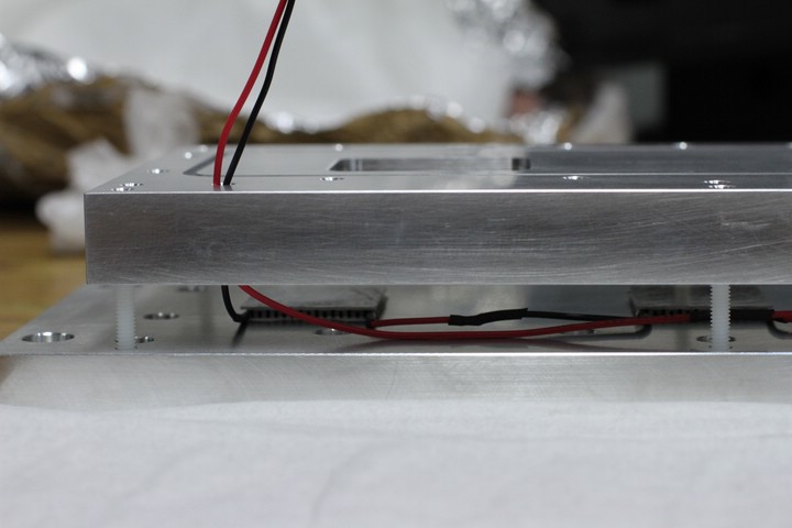
Feed the TEC wires through the access hole.
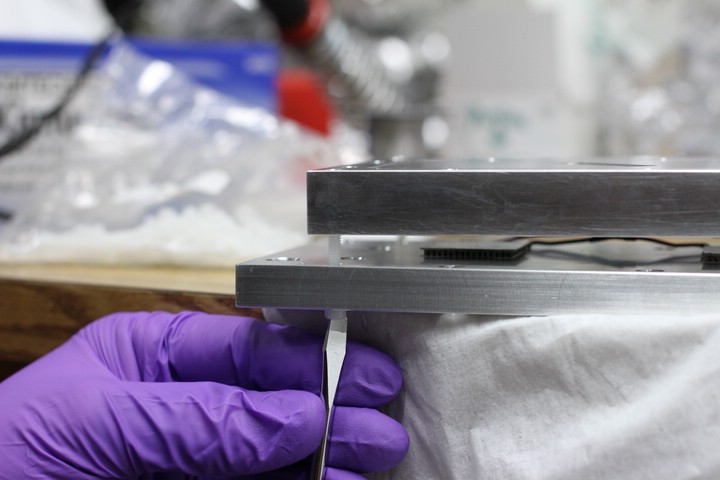
Loosly fitting the screws...
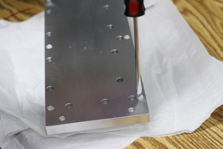
...then tightening them in a star pattern to ensure even pressure on the TECs.
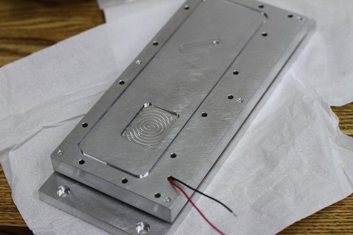
Assembled base, bottom cover, and TECs.
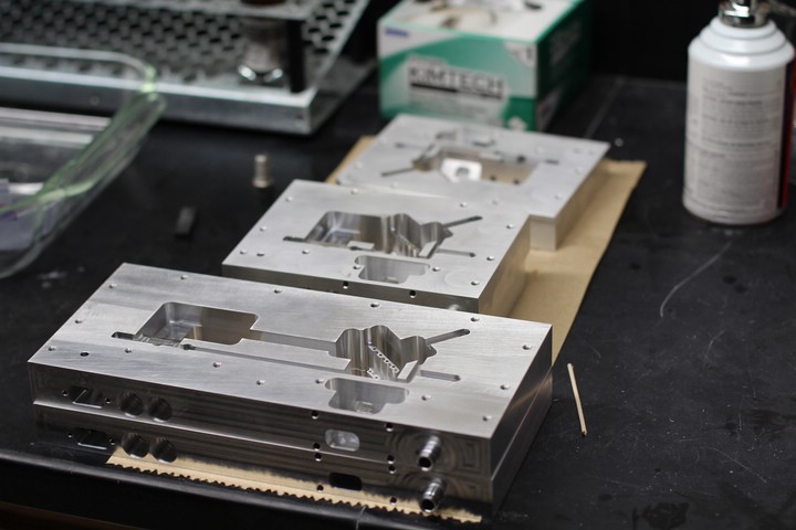
The laser cavities are finally back from the machine shop!
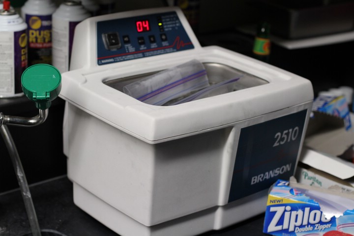
Sonicating parts. See top of page for cleaning details.
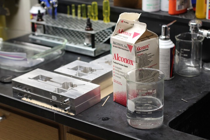
Alconox removes the majority of the machining oil.
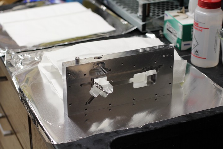
Prep for the next cleaning stage.
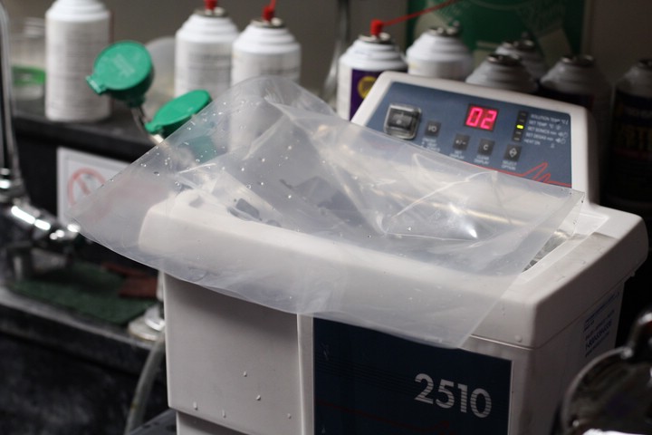
The long cavity was difficult to fit in the sonicator.
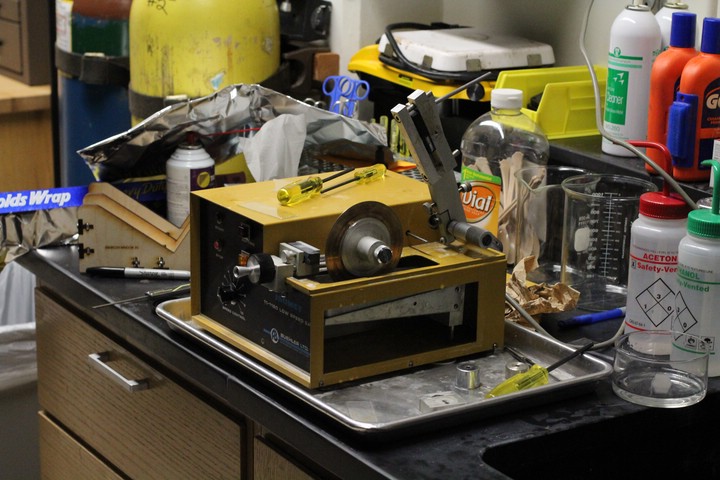
Diamond impregnated copper-beryllium blade used for glass cutting.
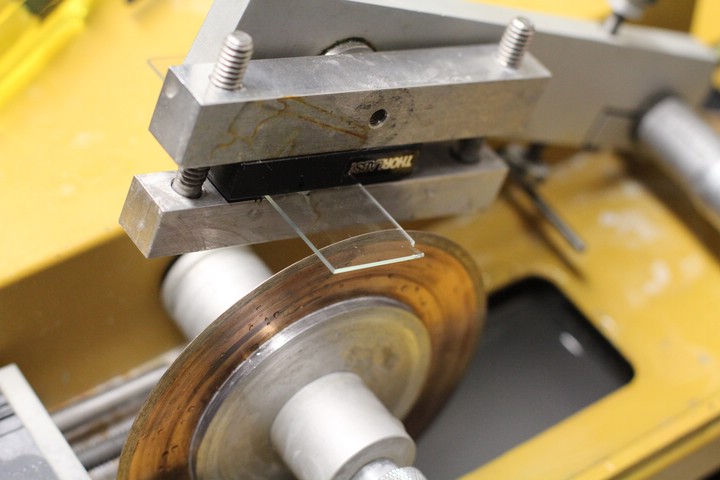
Fitting a microscope slide for cutting.
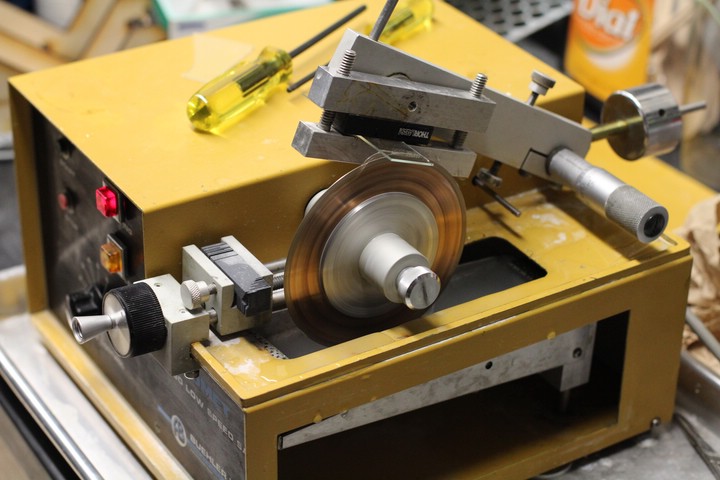
Cutting the slide to 0.70" square.
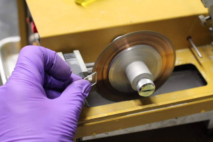
Removing sharp edges.
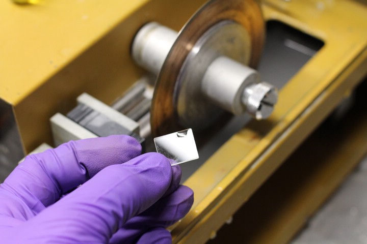
Completed window. After cutting, diamond powder remains on the glass surface which can scratch it, so it is important to only touch the edges until this can be washed off.
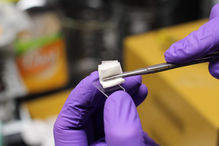
Ultra-pure methanol and lens cleaning paper gets things as clean as possible.
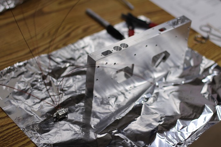
Kapton-coated wires for high vacuum use attached to a male DB-15 connector. Leave some excess length so the wires can be trimmed to an appropriate size later.
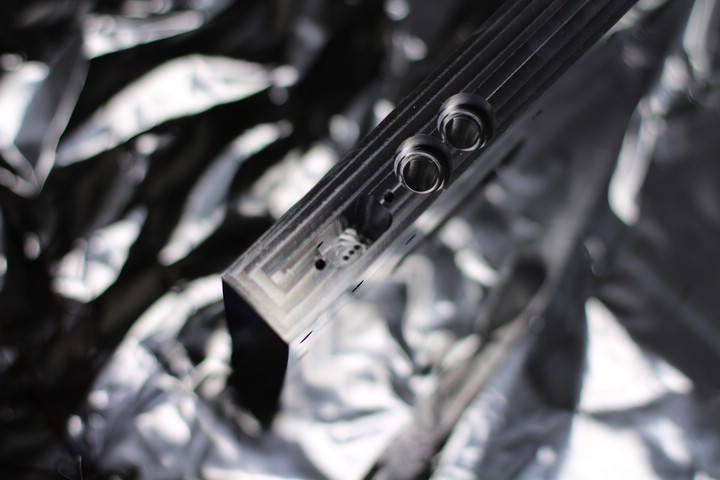
The wires must be fed through small holes. This makes it easier to pot them in epoxy.
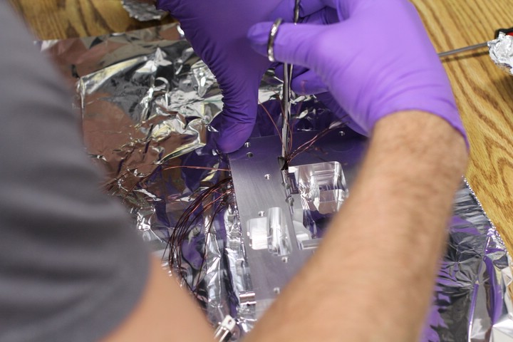
Using forceps to draw the wires though the small holes.
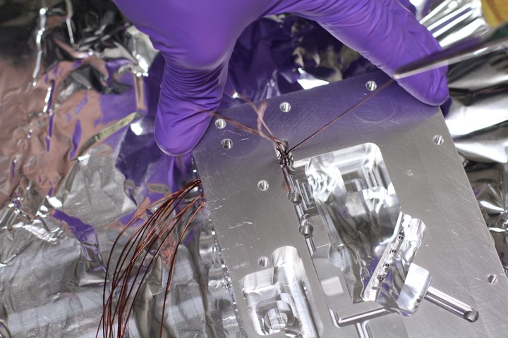
There are five pairs of wires and five holes, so we tried to feed matched pairs. This isn't extremely important.
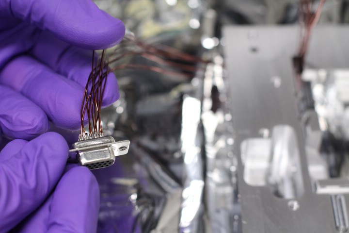
The wires have been threaded, now to pull them through to the proper length.
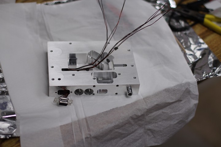
Make sure to leave enough wire on the connector side to work with if necessary.
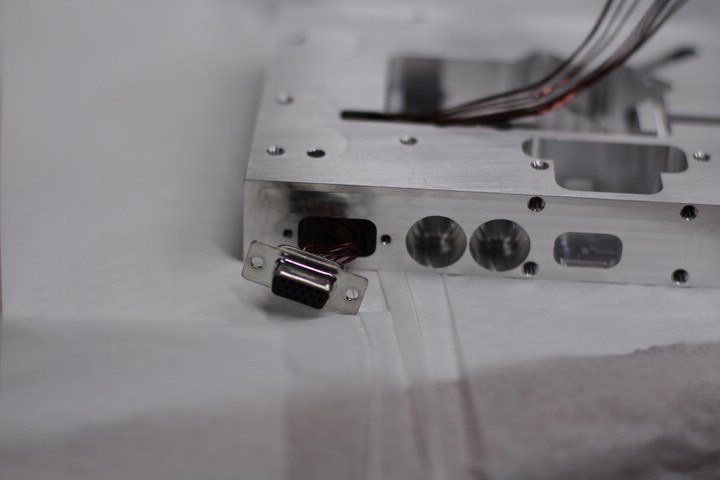
Wires were bent into an S shape inside the connector receptacle.
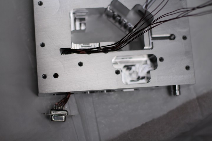
Wires and connector in place.
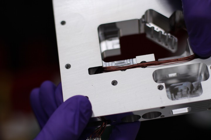
The potting epoxy tends to climb the wires so make sure the wires point in the proper direction.
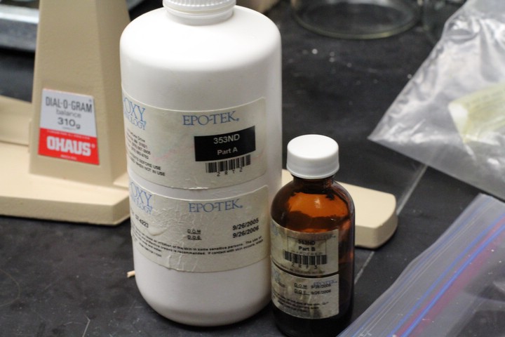
Epo-Tek 353ND vacuum safe epoxy.
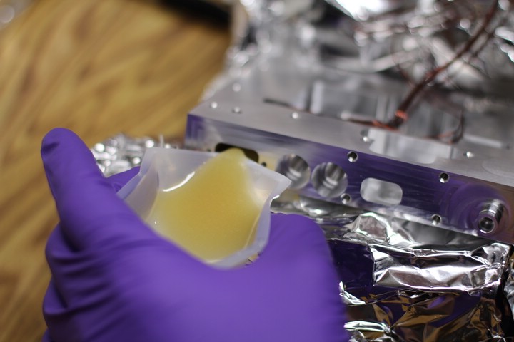
Epo-Tek epoxy to seal the wires in place and allow a vacuum.
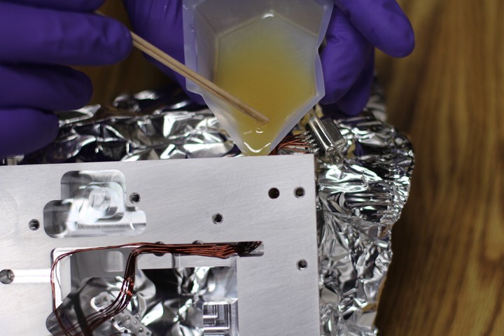
Pouring the epoxy in didn't work so well. It flowed though the TEC access hole and got on the lower surface. This needed to be scraped off with a razor blade. To avoid this we ended up using a syringe.
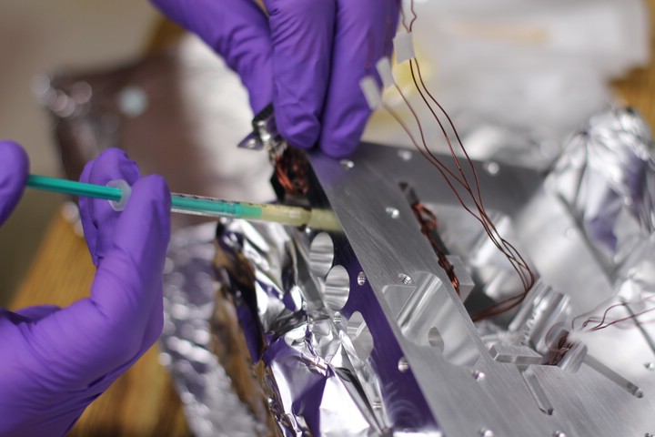
Incidentally, it takes about 2mL of epoxy to completely pot the wires.
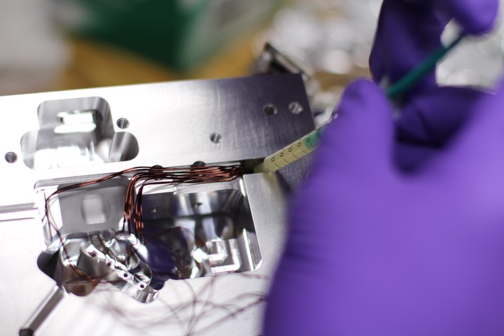
Applying epoxy to both sides of the wires.
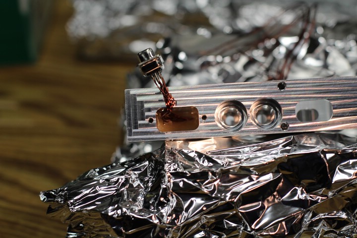
Potted wires. The cavity is propped up by Paul's Brewster Window Jig so the epoxy makes a good seal.
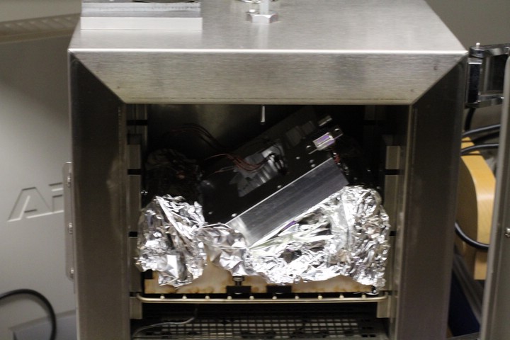
The epoxy cures much faster when baked. The oven was set for ~80C.
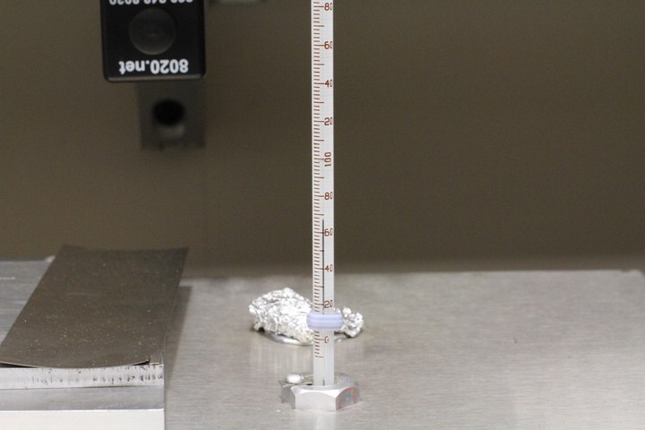
Mercury. Sweetest of the transition metals.
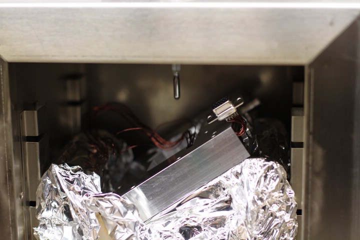
Baking. This takes around an hour depending on temperature.
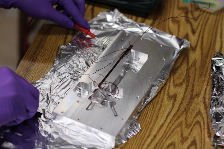
After pulling the wires through and before the epoxy set, we tested for continuity between the wires and the cavity body, which would indicate damaged Kapton insulation. Jiggling the wires until the epoxy came between the exposed copper and the aluminum solved this problem if it came up. But this only works before the epoxy sets.
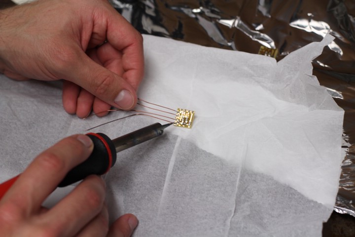
Preparing the internal circuit boards that filter the laser diode current.
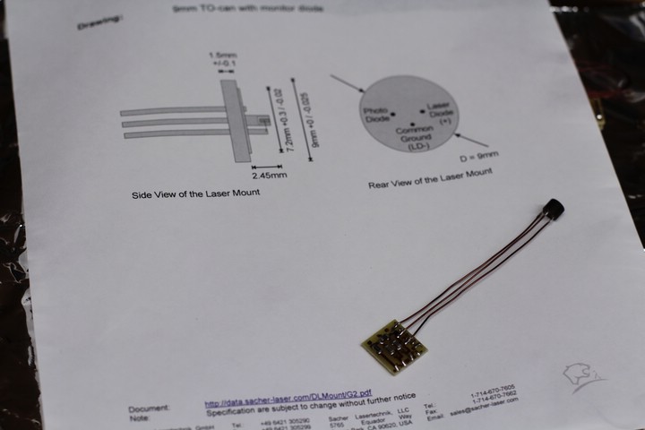
3-Pin diode laser connector.
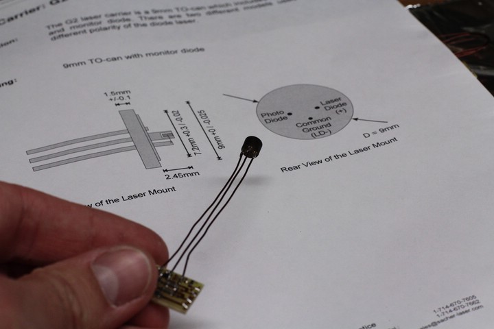
Making sure the connections are right. (Edit: The connections are WRONG in this documentation! The photodiode pin should be connected to "Photodiode-" instead of "Photodiode+").
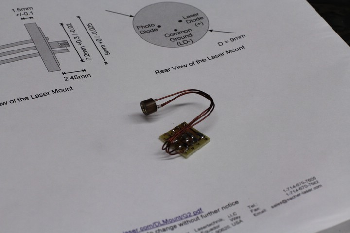
As much wire as possible was left on all internal connections to allow for easy collimation of the laser diode and other adjustments.
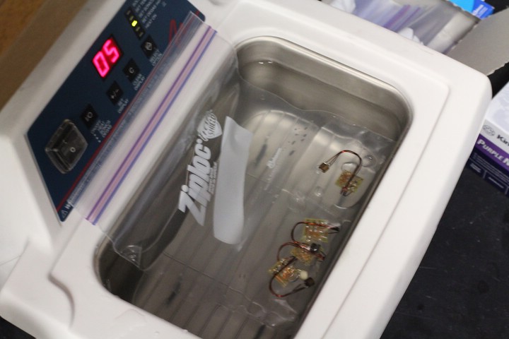
Sonicating the internal circuit boards in methanol only. Acetone may damage the components or the board itself.
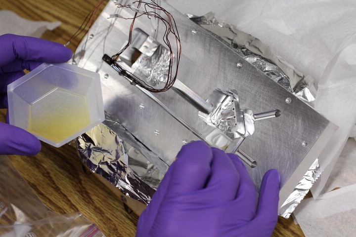
Epo-Tek epoxy for the Brewster window.
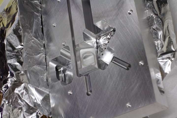
Just a thin, even ring around the port.
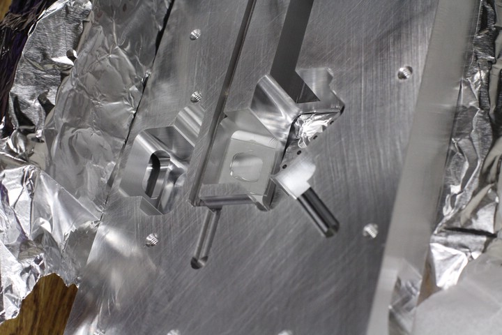
A forceps was used to position the window. DO NOT get any epoxy on the window where the laser beam will pass.
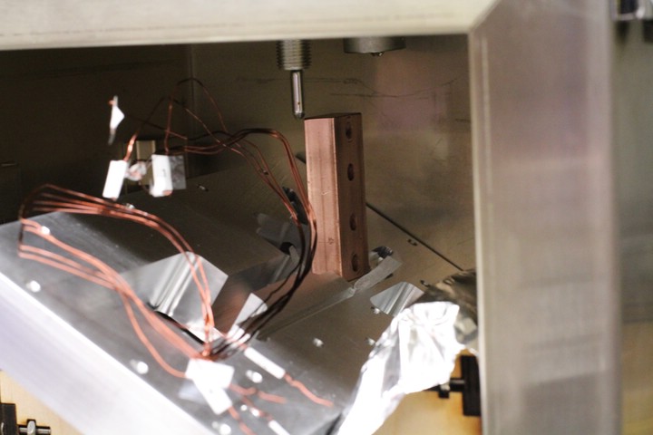
The whole cavity was placed on Paul's Brewster Window Jig which is designed to hold the window perfectly horizontal. A small chunk of brass wrapped in lens cleaning tissue was placed on the Brewster window, and a large piece of copper was placed on top of that. This supplied the pressure to ensure that the window adhered at the proper angle.
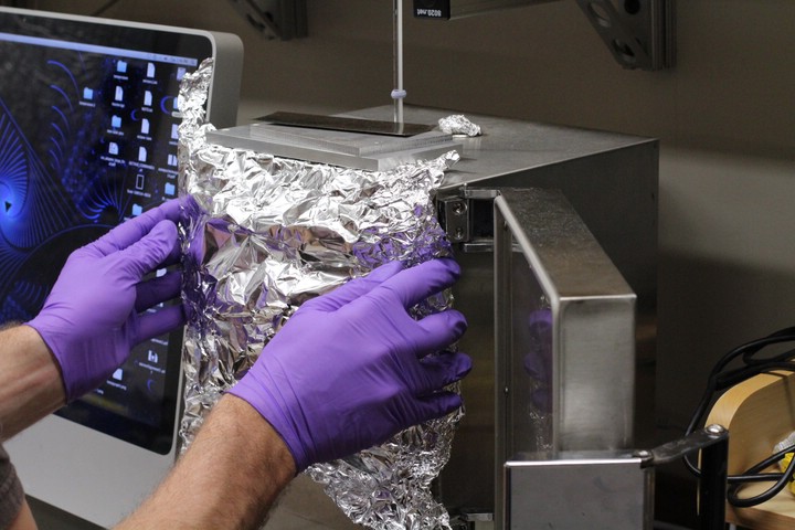
Improvising an oven door. The long cavity didn't quite fit.
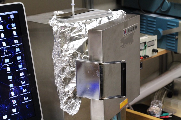
Long cavity baking. The foil worked well.
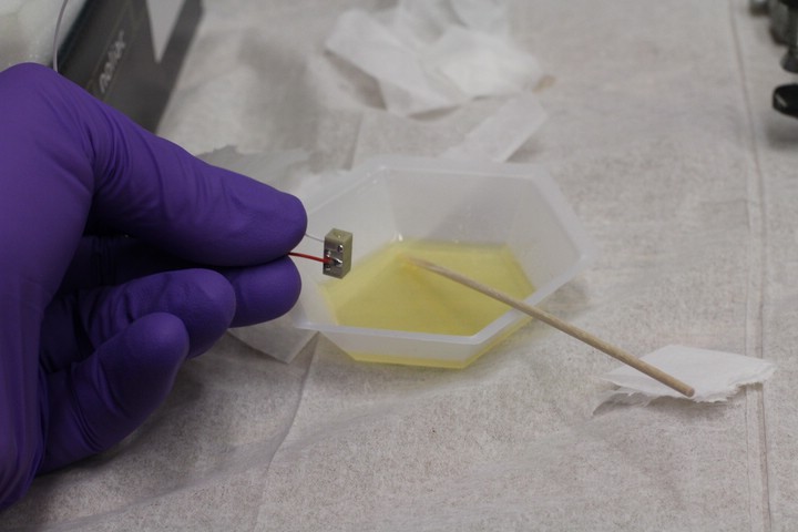
Piezomechanical actuator. The ends are pretty flat, but they need to be reinforced with sapphire discs, which are perfectly flat and distribute the pressure from the fine adjust screw. The discs are attached with the Epo-Tek epoxy.
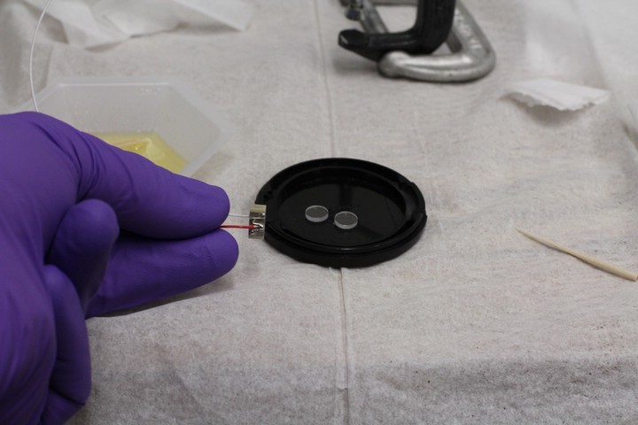
About to affix the discs to the piezo.
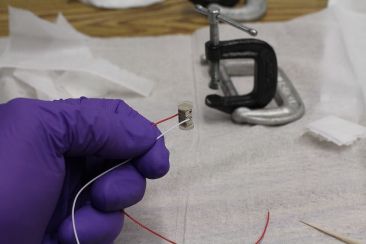
Atmospheric pressure is enough to hold the discs in place for now, but they need to be clamped and baked. Hence the clamp.
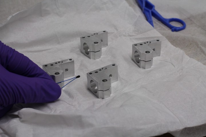
Diode Canister Mounts and thermistor.
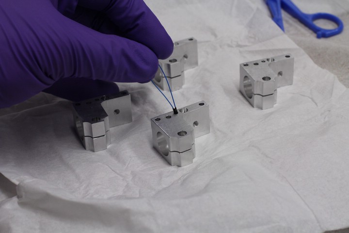
Inserting the thermistor.
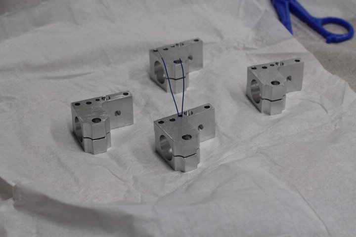
Thermistor inserted. A small dab of Epo-Tek epoxy was applied to the tip to keep it in place and to make good thermal contact.
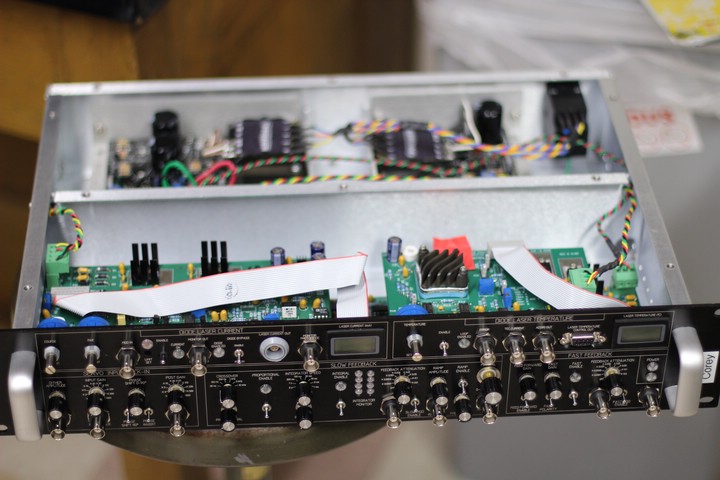
Here's a master laser driver that was prepared earlier.
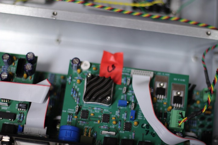
The temperature control boards were calibrated last year and the AD590s sealed with the board they were calibrated with.
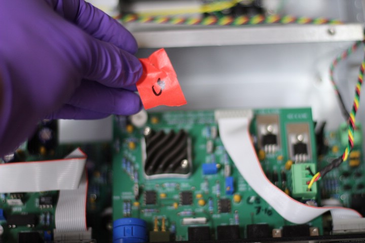
This is the AD590 from Corey's temperature board.
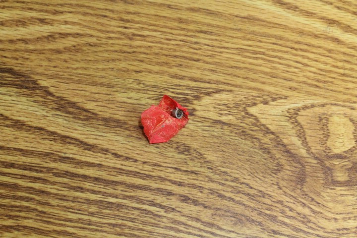
After a year, the adhesive was pretty caked on. Sonication in acetone was necessary.
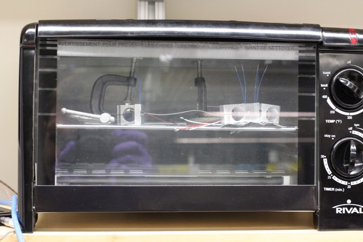
The AD590s and thermistors are installed in the diode can mounts, and are baking in the reflow oven using a modified reflow program named "Piezo". This baked them at 90C.
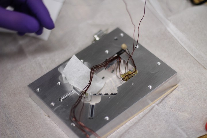
Installing the internal circuit boards. Note that you should leave some extra slack in the wires. The wires can be nicely nestled inside the cavity, but at this point you want to make sure that the board and diode can be moved far enough away from the laser body for collimation and polarization alignment (see later photos).
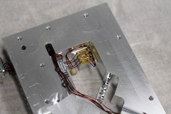
Installed internal circuit board.
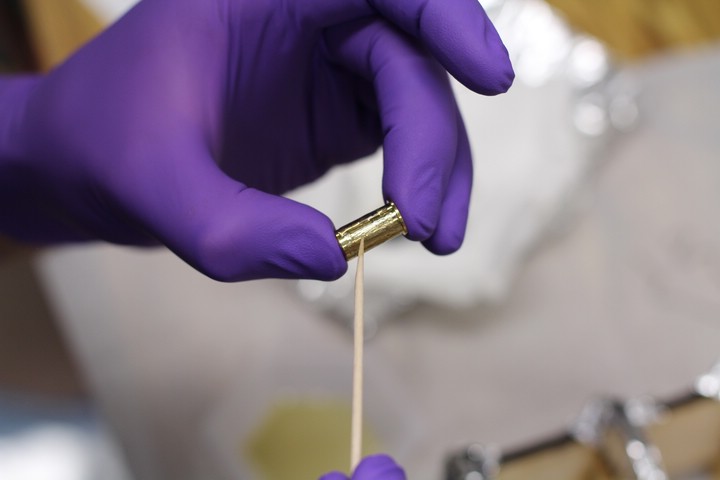
Coating the receptical for the fine adjust screw in Epo-Tek epoxy.
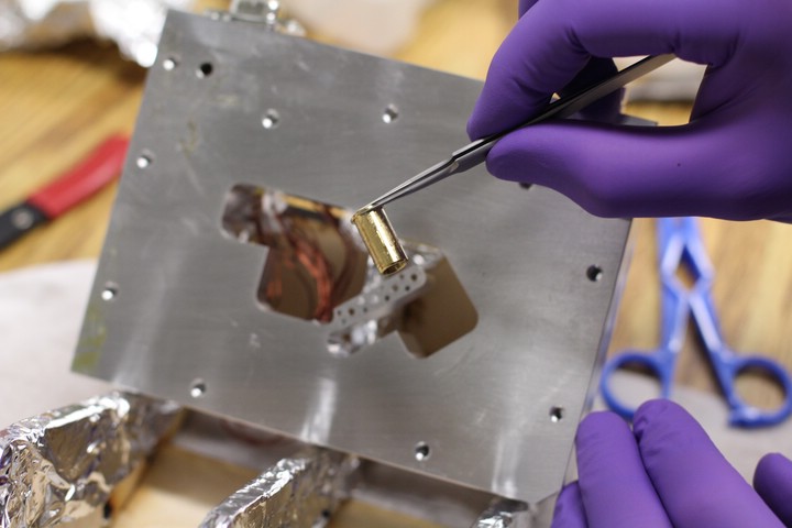
Coated fine adjust screw receptacle. There wasn't a lot of room to spare, so tweezers were necessary for insertion.
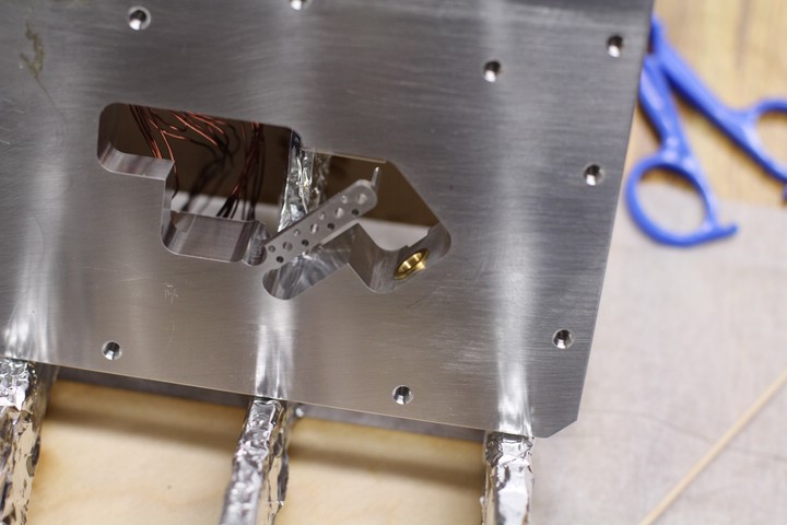
Inserted receptacle. Turning the piece several times while inserted ensures the epoxy is making good contact with the aluminum body.
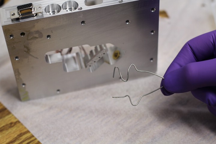
Receptacle clamp. Ingredients: 1 Paper clip, 1 MacGyver.
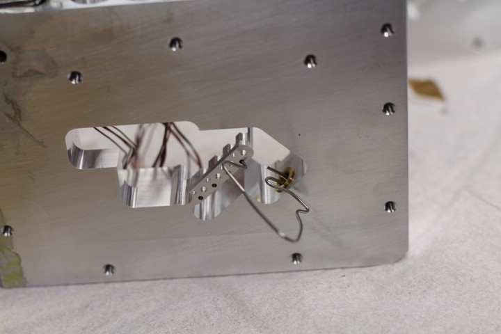
Clamped receptacle.
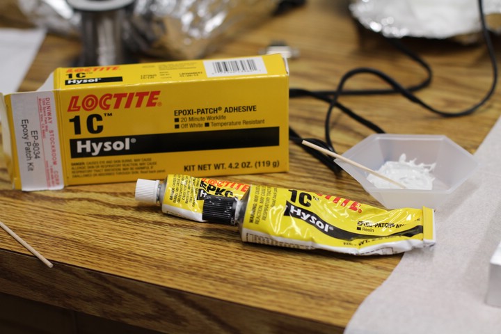
This is the Loctite equivalent of Torrseal epoxy.
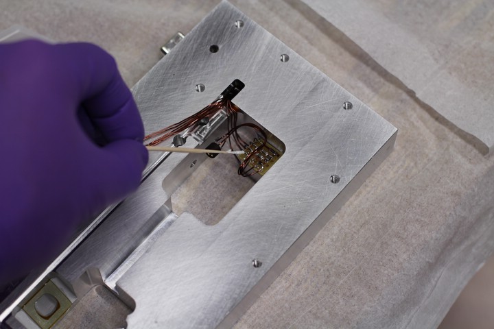
Applying Torr-Seal to reinforce the soldered connections to the internal PC board.
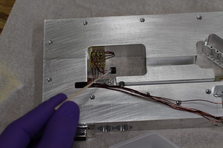
Reinforcing connections allows for easier adjustments such as beam collimation later.
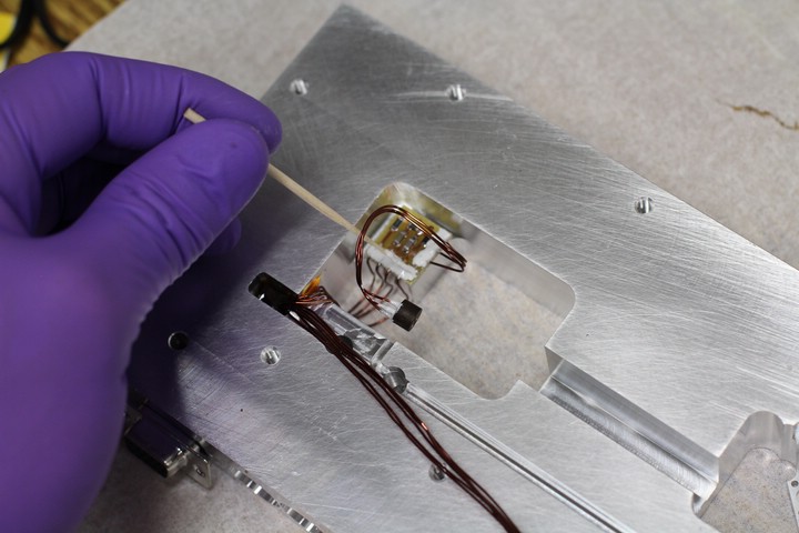
More epoxy.
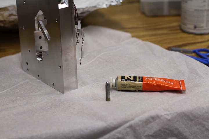
Vacuum-safe grease and sonicated fine adjust screw.
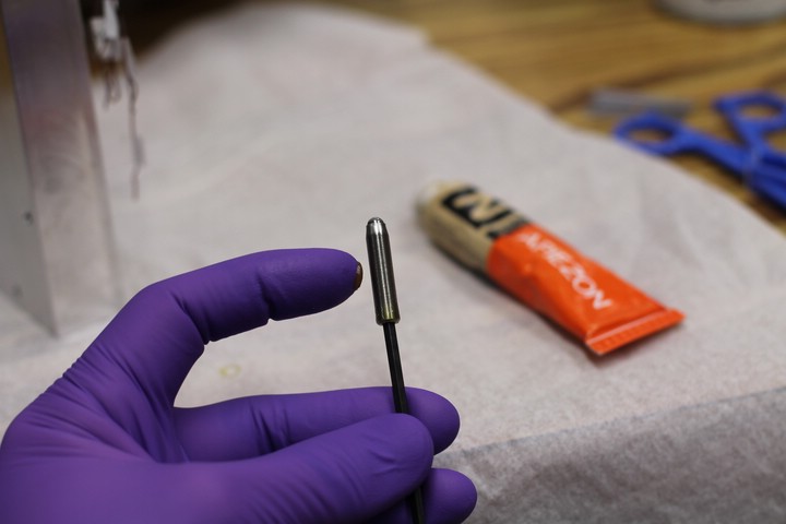
Apply vacuum grease to the fine adjust screw.
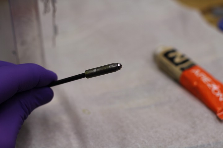
Make sure all the threads are coated.
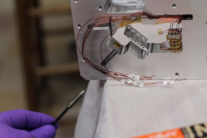
Insert the fine adjust screw into its receptacle.
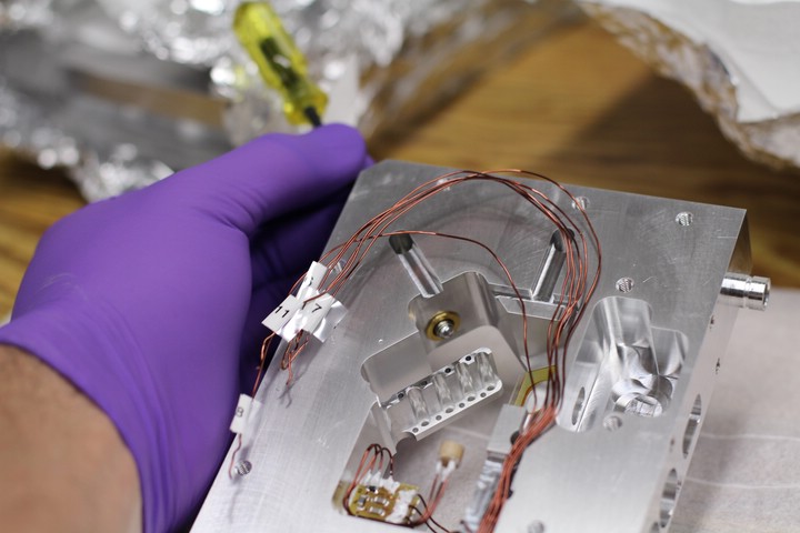
Inserted fine adjust screw.
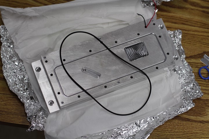
Vacuum-safe rubber O-ring.
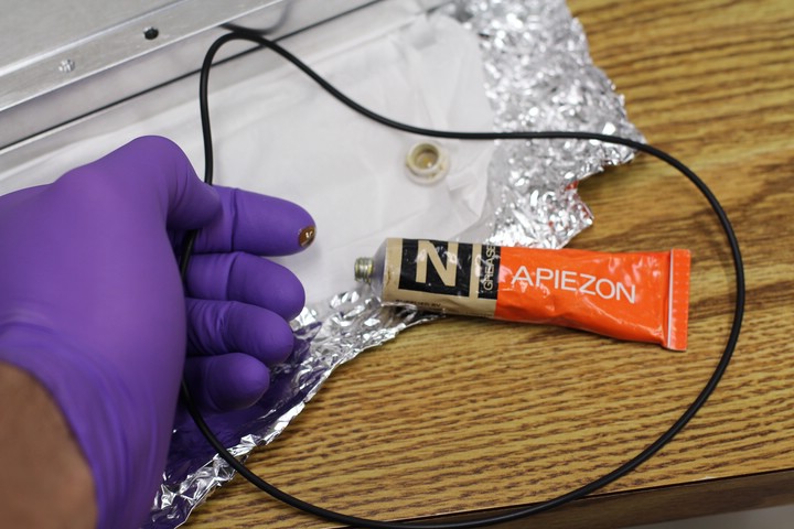
Apply vacuum grease liberally.
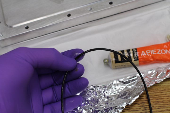
Make sure it gets an even coat.
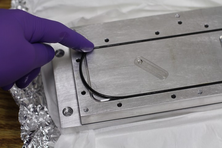
Insert the O-ring into the groove in the bottom cover.
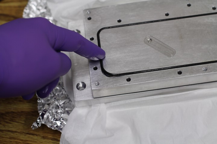
It fits!
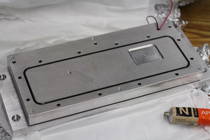
Bottom cover with greased O-ring, base and TECs, ready for attachment to the laser cavity. For models with an O-ring under the diffraction grating arm, this is a great time to place it. NO grease is applied to the grating arm O-ring.
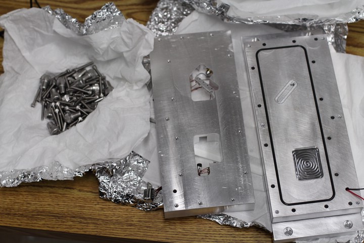
About to line up the cavity with the bottom assembly.
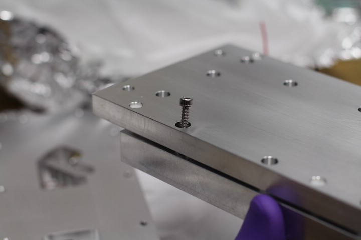
Loading the screws and lowering the bottom cover onto the cavity worked well for proper alignment.
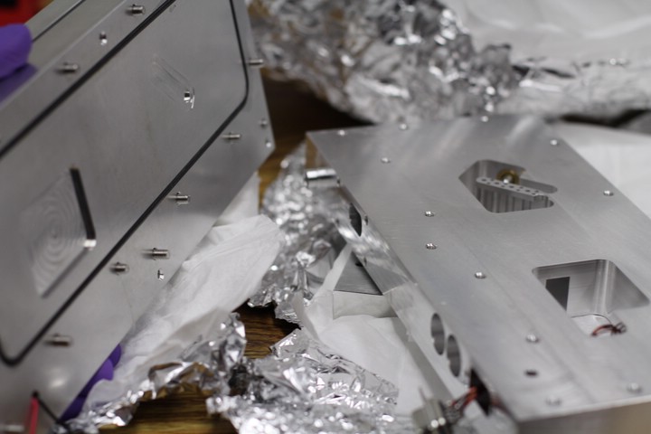
Lining things up.
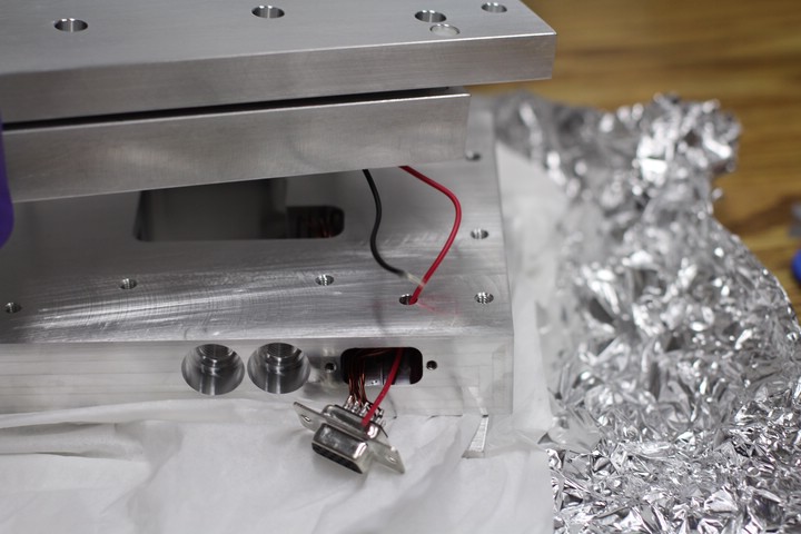
The TEC wires must be fed into the DB-15 connector port.
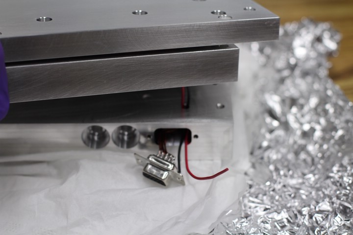
Trying not to squish the wires.
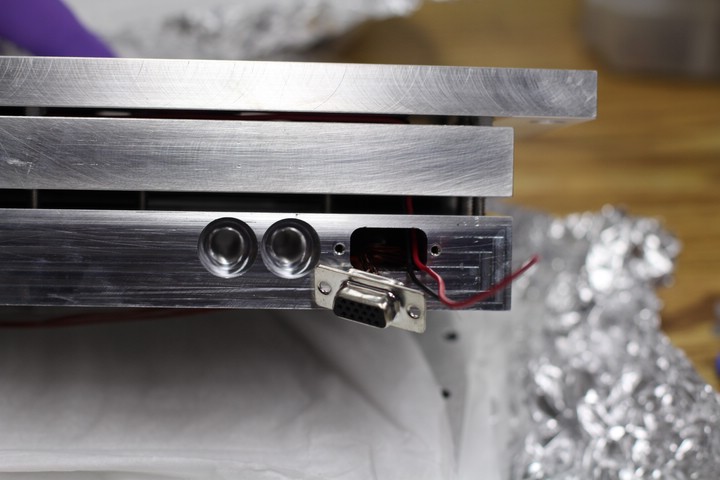
Everything lines up ok.
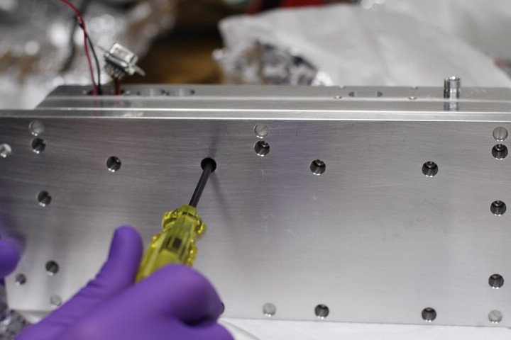
The screws are tightened in a star pattern. This ensures an even seal all around.
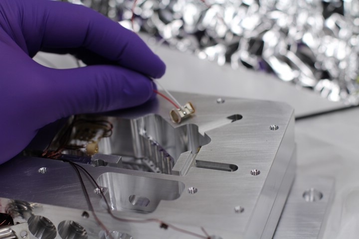
Assembled piezo with sapphire windows.
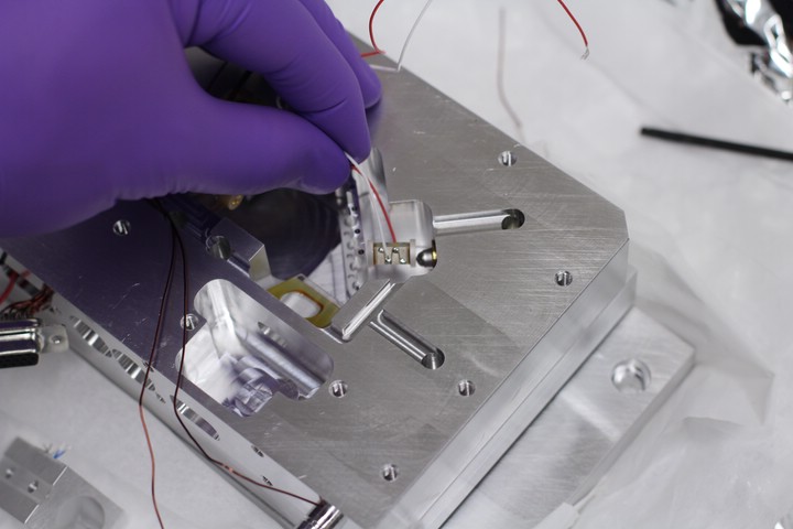
The piezo is placed between the fine adjust screw and the diffraction grating arm. No epoxy necessary, it's held in place by friction.
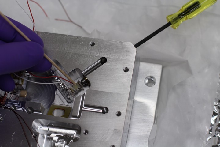
Try to get the piezo centered on the fine adjust screw. Carefully remove factory red and white leads and attach appropriate Kapton wires (the dots on the side with the red wire indicate the positive electrode)
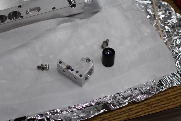
Diode can mount with epoxied AD590 and thermistor, diode can, and two 3/8" 8-32 machine screws.
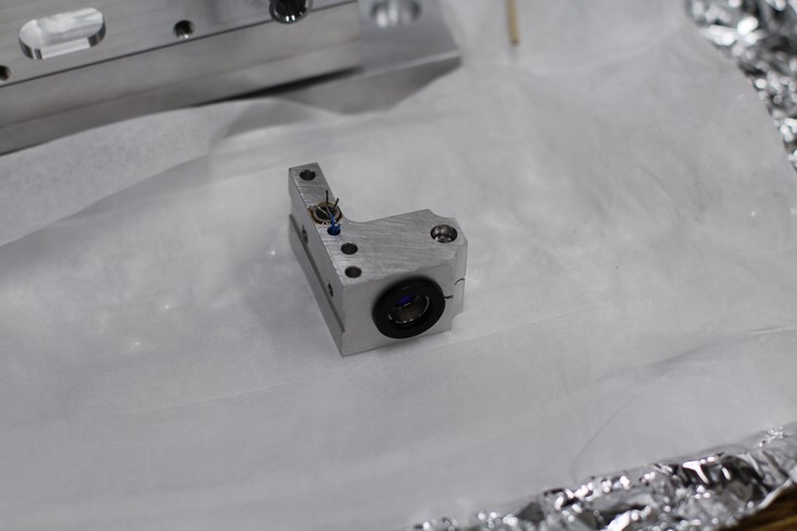
Completed diode can mount, ready for installation in the laser cavity.
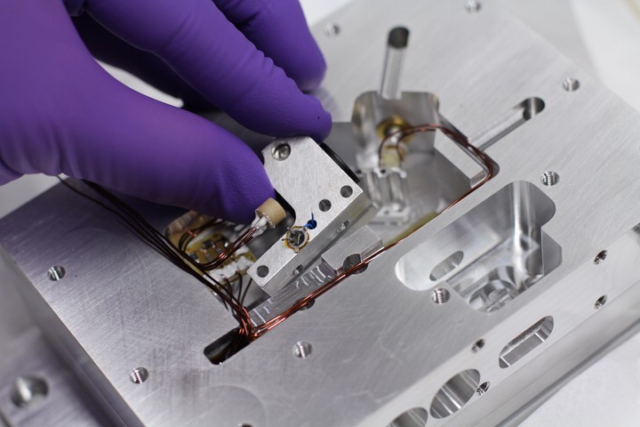
Installing the diode can mount.
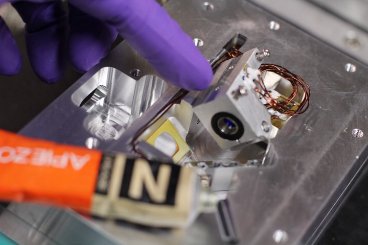
Apply a thin layer of vacuum grease to the contact surfaces to help with thermal conductivity.
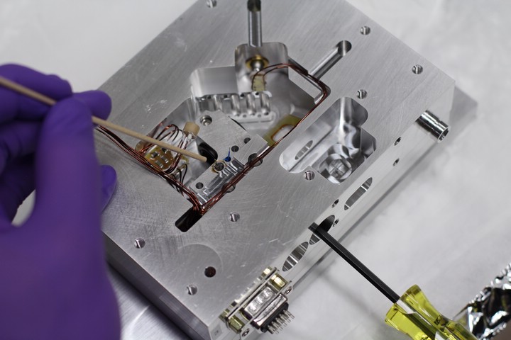
Threading the 8-32 machine screws.
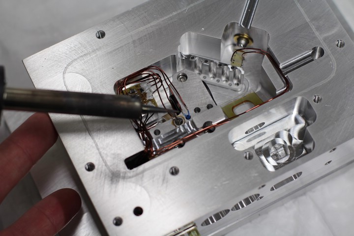
Soldering the Kapton wires to the AD590 and thermistor.
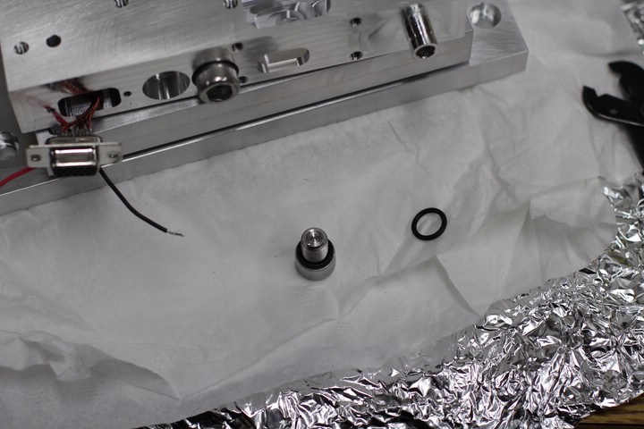
These large machine screws seal the diode can mount screw ports, as well as the fine adjust screw port (apply vacuum grease to O-rings, and do not overtighten).
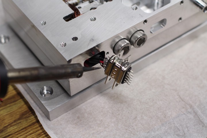
Soldering the TEC wires to the proper pins on the DB-15, and applying heat shrink tubing.
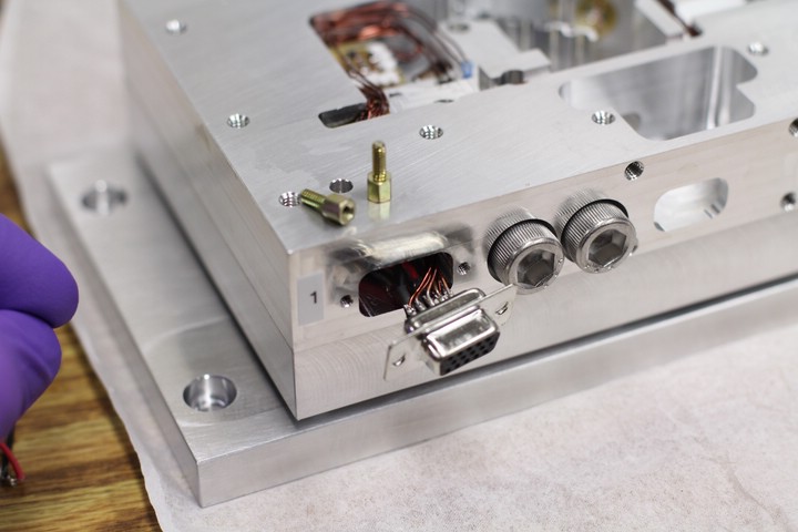
Completed DB-15 and jack screws.
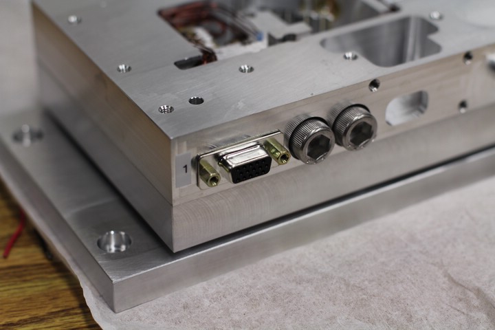
Finallized connector.
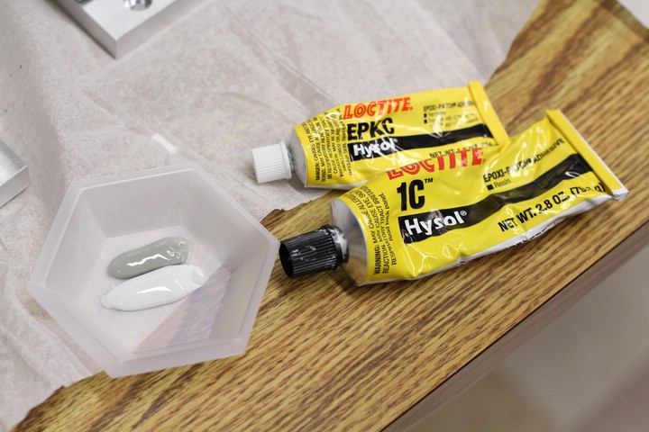
More Torrseal to reinforce the AD590 and thermistor connections.
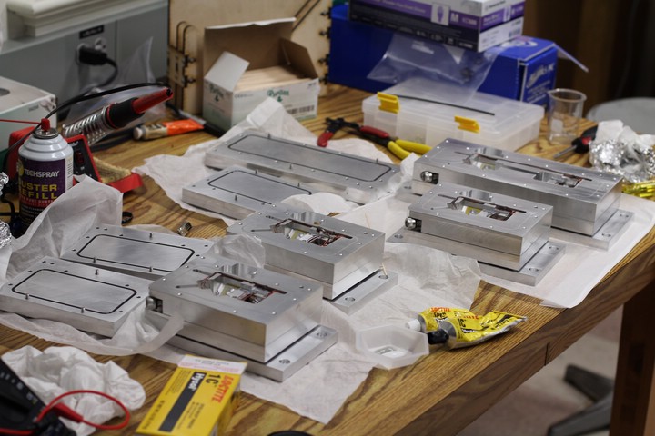
Applying Torrseal to all four of the lasers at once.
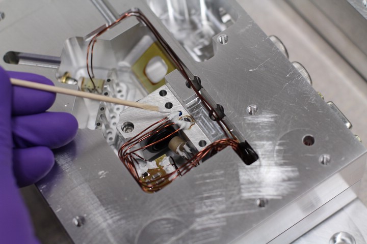
Putting a lot of Torrseal on the delicate connections.
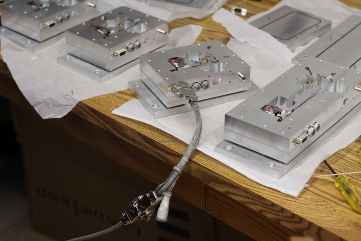
Connecting the laser to a temperature control board to test the TECs. After about a minute the body is cold and the base is warm. Looks good.
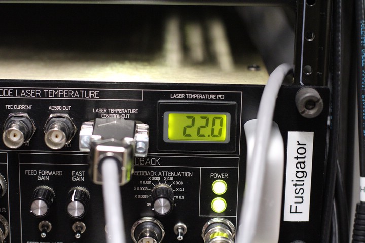
Temperature readout is good.
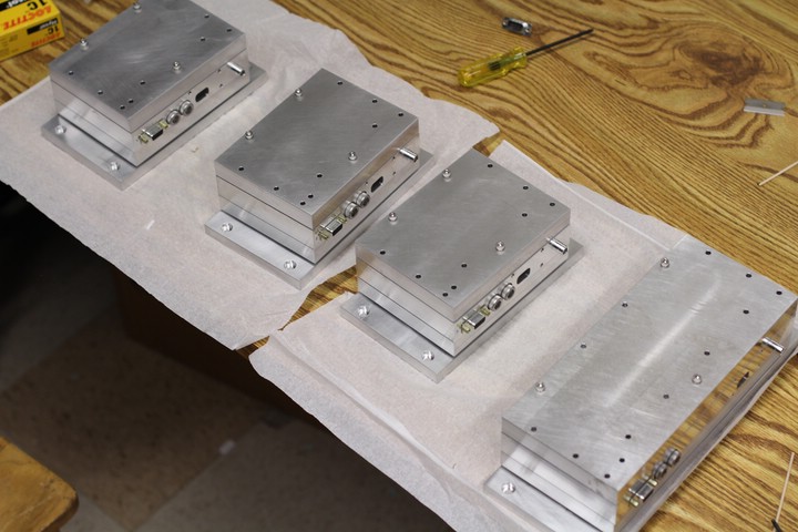
Four semi-complete lasers await laser diodes, diffraction gratings, and anamorphic prisms.
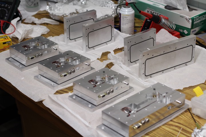
Family photo.
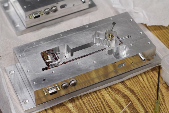
Shot of the long cavity laser.
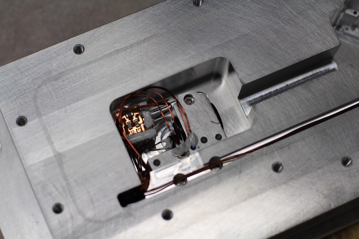
Close up of the diode can mount and internal PC board.
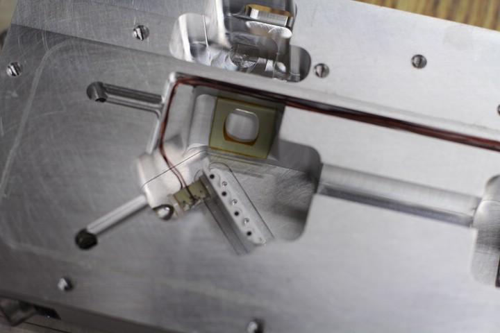
Close up of the piezo and Brewster window.
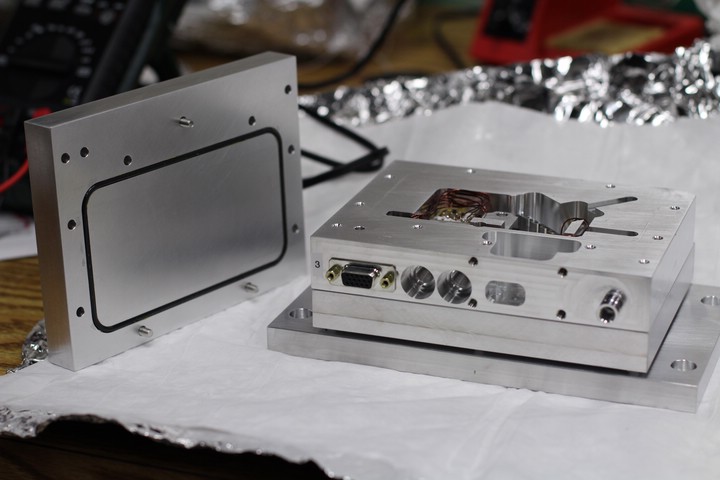
Short cavity laser.
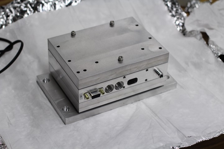
Short cavity laser.
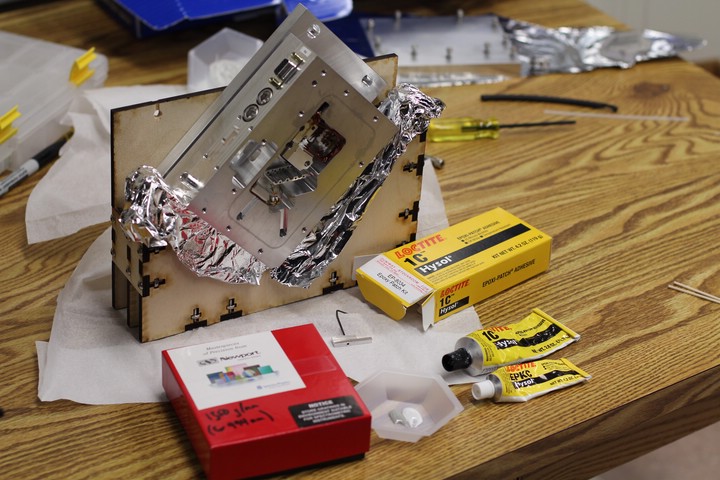
Preparing to install diffraction gratings. Each grating was calibrated for certain wavelengths.
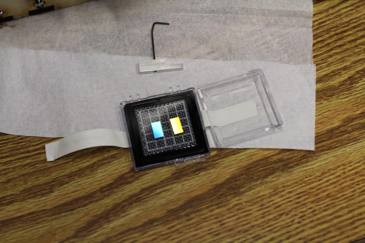
1500 lines per millimeter looks pretty good. Hold the grating by the edges so more lines aren't added.
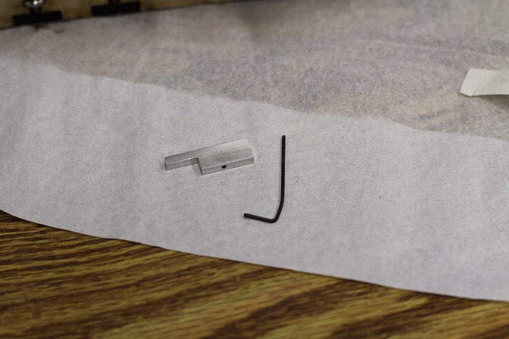
Diffraction grating jig. This holds the grating precisely horizontal and centered.
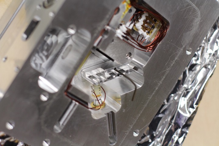
Only one thing can go here...
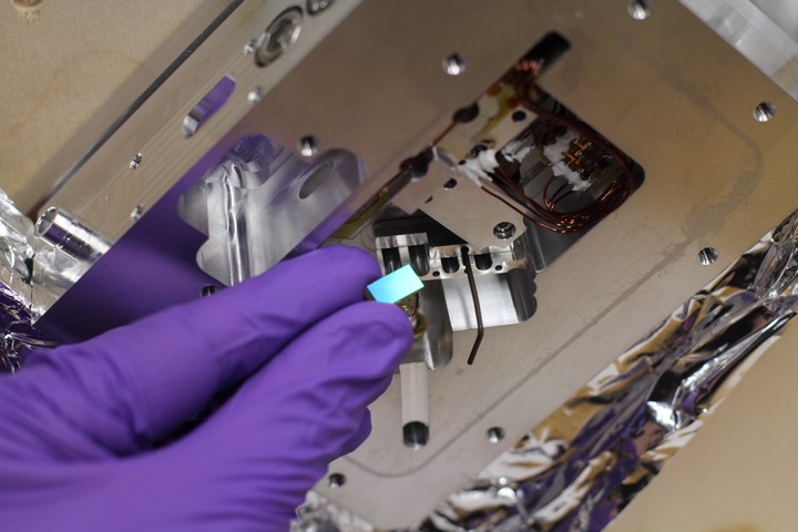
Carefully placing the grating on the arm.
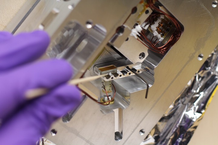
Applying a small amount of Torrseal to the edges of the grating only. Don't get any underneath the grating. Its best to use a small amount that can be easily removed until the grating can be tested.
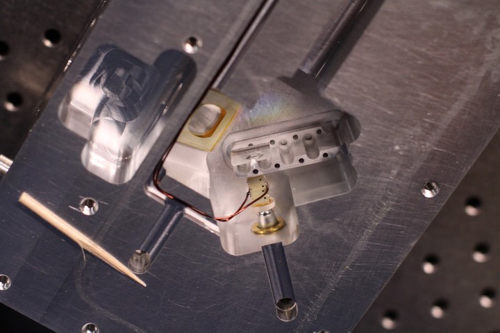
Removing the jig without scratching the grating can be tricky.
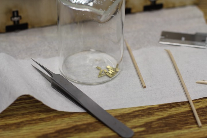
The 994nm laser is powered by a 1030nm diode. Since a large frequency shift is required, a high grating angle is needed. To avoid unduly bending the grating arm, we shimmed the grating with 0.020" shimstock.
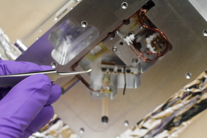
Placing the shim is tricky. Tweezers are your friend.
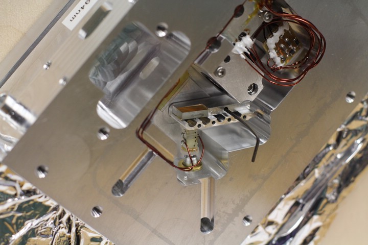
The shim is in place, but the epoxy is tacky and tends to move small objects around quite a bit. Patience and a steady hand are key.
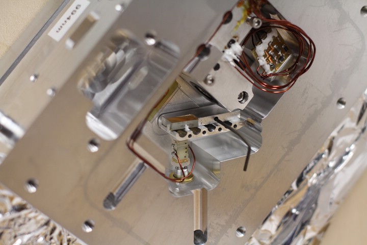
Whew, epoxy is in place and everything looks ok!
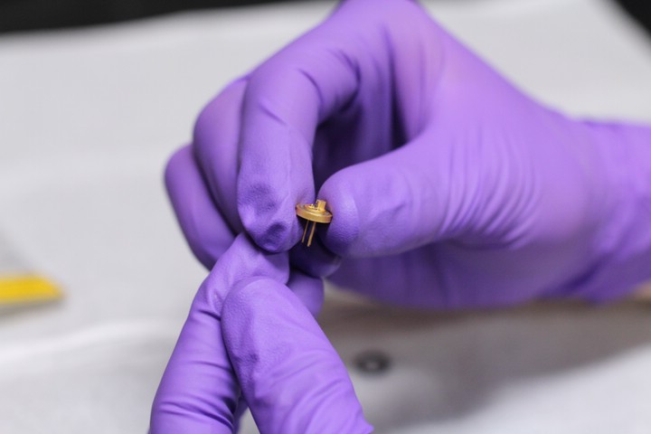
This is the fancy diode laser. Make sure you are GROUNDED before you touch this to protect the diode. We used a long wire attached to the optics table, then wrapped around our wrist.
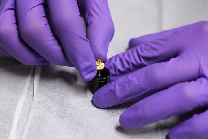
Installing the laser diode in a diode canister with a collimation lens.
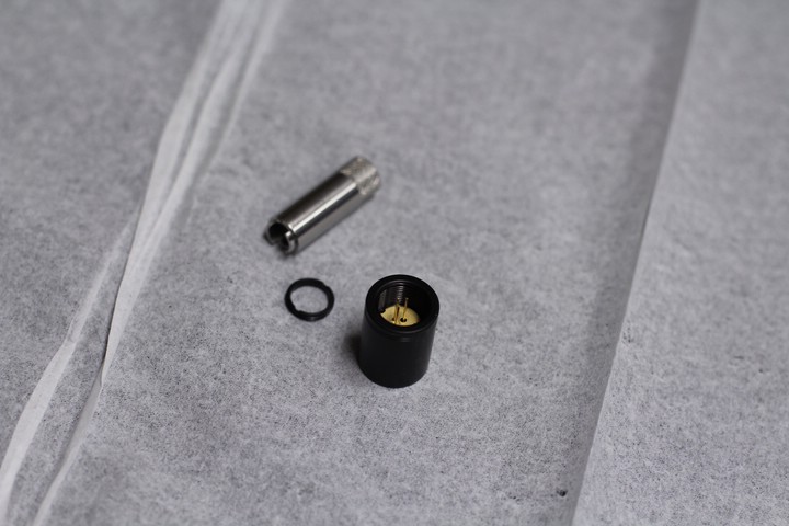
Diode can, laser diode, wrench, and retention ring.
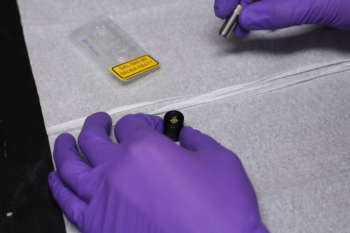
About to tighten the retention ring.
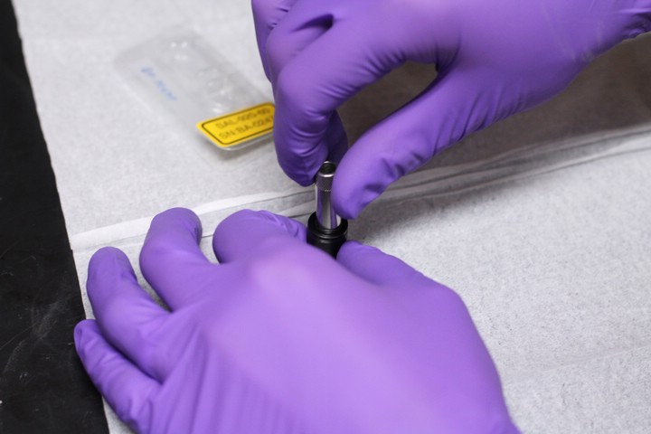
Tightening the retention ring. This should be quite snug, but only by hand.
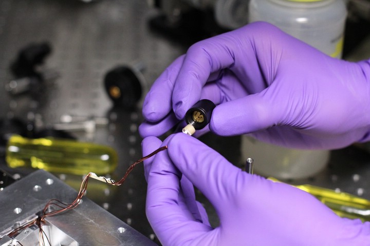
Plugging the laser into the 3-Pin receptacle.
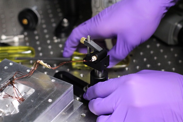
Steadying the diode can for collimation.
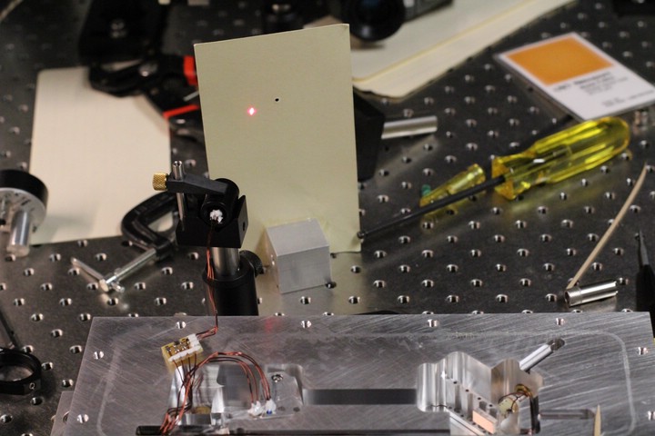
It works! The beam was shot down a long hallway, and the front of the diode can was adjusted until the laser was collimated. Make sure there is no focus in the beam, and that the beam maintains its shape. Slight distortions are unavoidable due to abberations in the lens, but a change from vertical to horizontal ellipticity indicates a poorly collimated beam. An extra set of eyes helps a lot for this step.
...Which reminds me, wear laser goggles!
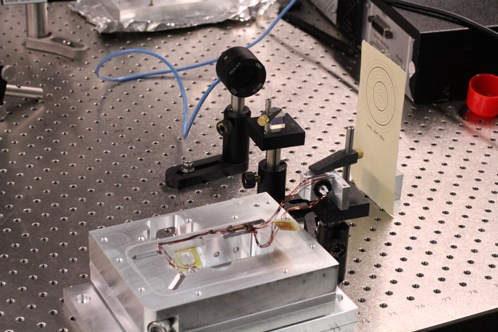
Install the diode can into the diode can mount and secure the diode can mount to an optics post.
To couple the beam into a fiber later on, maximum power is realized when the beam is circular. However, the freshly collimated beam is elliptical. To correct the shape of the beam, we use horizontally aligned anamorphic prisms. For these to operate properly, the elliptical beam must have its long axis aligned horizontally. We use polarization to accomplish this alignment.
In a Polarized Beam Splitter, vertically polarized light is reflected and horizontally polarized light is transmitted. Due to quantum effects, the laser is polarized parallel to the short axis of the elliptical beam. Aim the beam into a PBS and use a power meter to measure the transmitted beam. Rotate the diode can within the diode can mount until the power meter reading is minimized, then secure the diode can with the clamping screw in the mount.
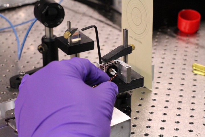
Rotating the diode can within the mount. We look to minimize the portion of the beam which is transmitted through the PBS. It is more accurate to minimize the transmitted horizontally polarized light than to maximize the reflected vertically polarized light, even though they are equivalent operations. When complete, the beam has its long elliptical axis aligned horizontally.
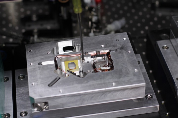
These temporary 4-40 machine screws allow fine adjustment of the laser tilt. They were rounded on the bottom in a lathe to minimize contact area.
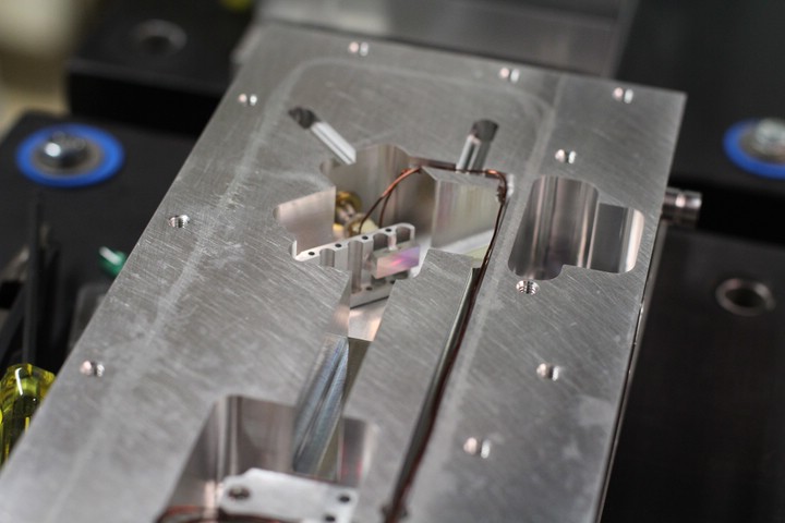
Use the tilt screws and the fine adjust screw to achieve feedback to the laser diode from the diffraction grating. The laser brightness will increase dramatically when proper feedback is achieved though a process called Thresholding.
-
The laser frequency needs to be tuned at this point. Couple the beam into a wavemeter and use the fine adjust screw to achieve an approximate desired wavelength. Since loss of threshold and changing angles are caused by this adjustment, much grumbling can be observed in the individual performing the calibration. Make sure you use an optical isolator for this step, since feedback from the fiber-couple is unacceptable.
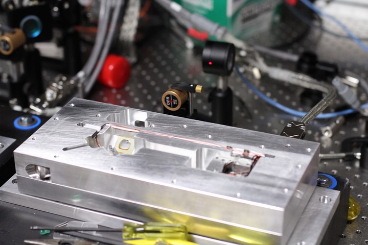
Once the rough wavelength is set, thresholding must be optimized. Modulate the laser current with a slow triangle ramp and output the beam to a power meter. The current modulation needs to cause the laser to repetitively jump to and from threshold.
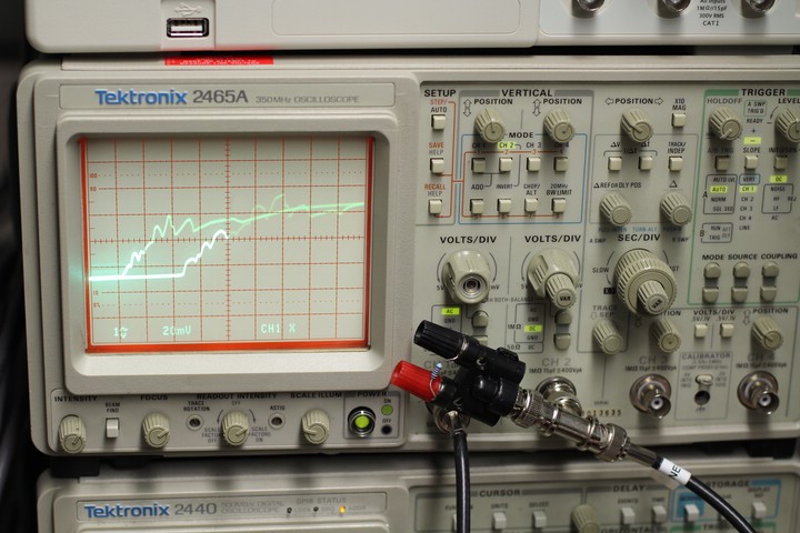
This is the plot of diode current vs. laser power. It's very sloppy, so adjust the tilt screws until threshold is achieved with minimum current and output has high slope.
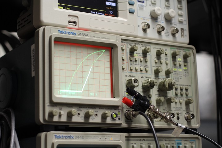
This is a much better signal. Though the 689nm laser had a lot of hysteresis even when optimized.
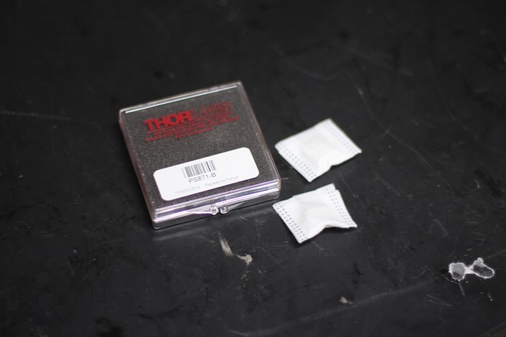
These are the anamorphic prisms. Or rather their case.
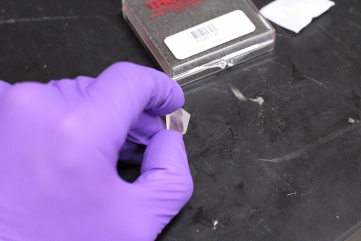
Try not to touch the optical surfaces.
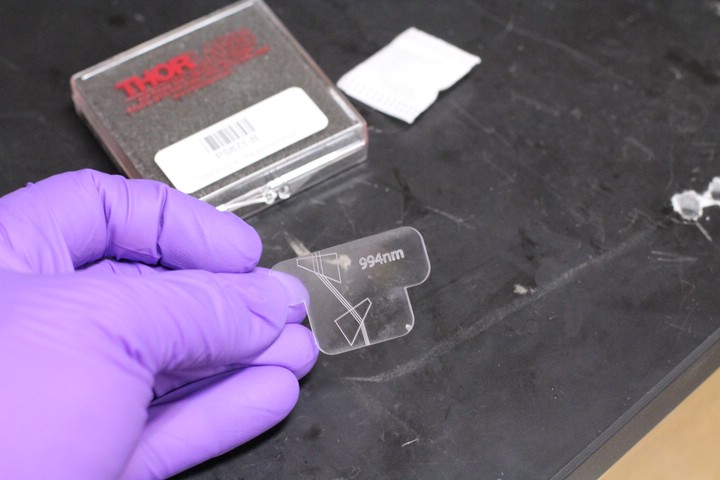
This is a prism guide that Paul designed. It was printed on acrylic with a laser printer in the architecture building. When the prisms are set over the outlines, the elliptical laser should be compressed into a circle. Each guide is calibrated for a specific wavelength.
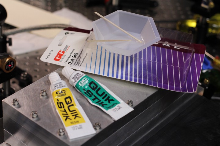
This is 5-minute epoxy. Nothing special since the prisms live outside the vacuum seal.
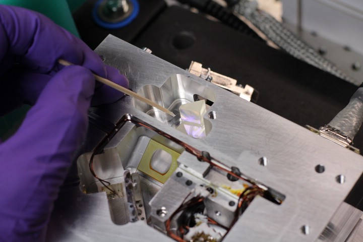
Place the prisms over the guide's outlines and ensure that the laser beam exits the laser directly over the lines in the guide to ensure that it will pass though the optical isolator. Also ensure the beam exits at a right angle to the housing. Three points of epoxy, one per corner, should be enough to set the prisms while still allowing for relatively easy removal if adjustments are needed.
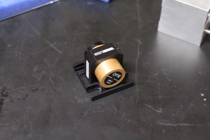
Thorlabs optical isolator with stock mount. There is a powerful magnet and fragile glass inside, so keep your ferrous tools away lest you damage something.
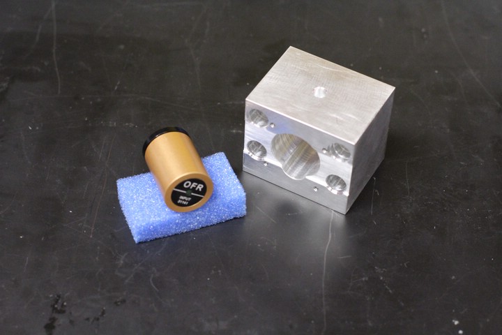
New isolator mount.
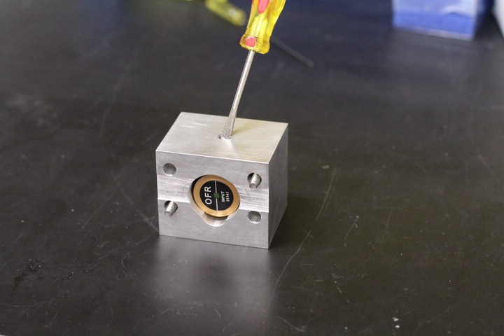
The beam must enter the isolator from this side. The white line should be as vertical as possible. The isolator is secured by a nylon set screw on top.
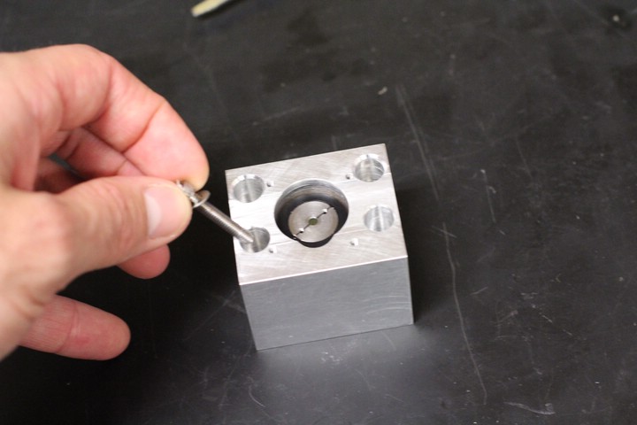
Ferrous material hazard.
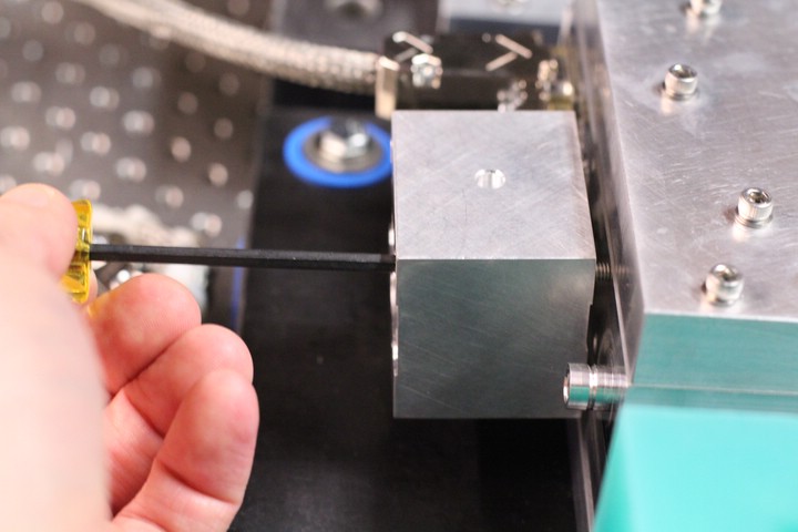
Bolting on the isolator. There is some play in the isolator, use it to align the isolator precisely in front of the beam.
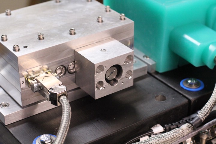
Completed Laser!