Tobias Brown-Heft
University of Oregon Atom Optics
In August 2013 I left the atom optics group to attend graduate school at the University of California at Santa Barbara. My advisor is Prof. Chris Palmstrom in the molecular beam epitaxy lab. My current information can be found here.
For files related to my projects, click here.
To see a nifty table of 3D animated hydrogen states I made while putting off a writing assignment, click here.
This site is mainly so I can avoid using the unix system, and also so that I can easily access my files from home. I will also update
this with my progress on certain lab projects so that when I leave, other people won't have
as much trouble finding stuff as I did.
Unibody Littrow Laser
Finalized construction and tuning of the new in-house designed littrow lasers.
These are designed with enough passive stability to be used for strontium atom optics experiments.
Wavemeter
The instruction manual for the Wavemeter can be found here.
This is a modified Michelson interferometer that was originally designed by Aaron Webster,
an undergraduate researcher. It's purpose is to determine the wavelength of an unknown laser source by comparing it to a known laser source. It does this by interfering the two beams with themselves and carefully changing their path lengths by equal amounts. Electronics count the number of fringes produced by translating
a retroreflective cart. The math simplifies to the proportion: λ2=λ1*N2/N1 where N is the number of fringes counted. The Webster got the device working, then abandoned the
project without documenting much of his work, and several individuals have been working to retrace his
steps. John Smith and Keith Fannin, UCORE students interning during the summer of 2011, translated
the rough board design into Osmond and ordered high quality PCBs. However, there were several errors in
the board that needed to be updated. These have all been fixed and the latest files can be found in the
"Files" section. These have also been updated to the wavemeter folder on the internal projects site.
The wavemeter is working for the most part. Feeding the two inputs from a single function generator
results in identical counts nearly every time. Several items needed to be adjusted to make it operational:
- Fixed bad ground connections, including missing ground pins on several ICs
- 5V rail to AND gate.
- Fixed cables for position sensors.
- Corrected Ethernut code with Jeremy's help. The AND gate now does what it's supposed to do, which
is shut off the counting while the cart reverses direction.
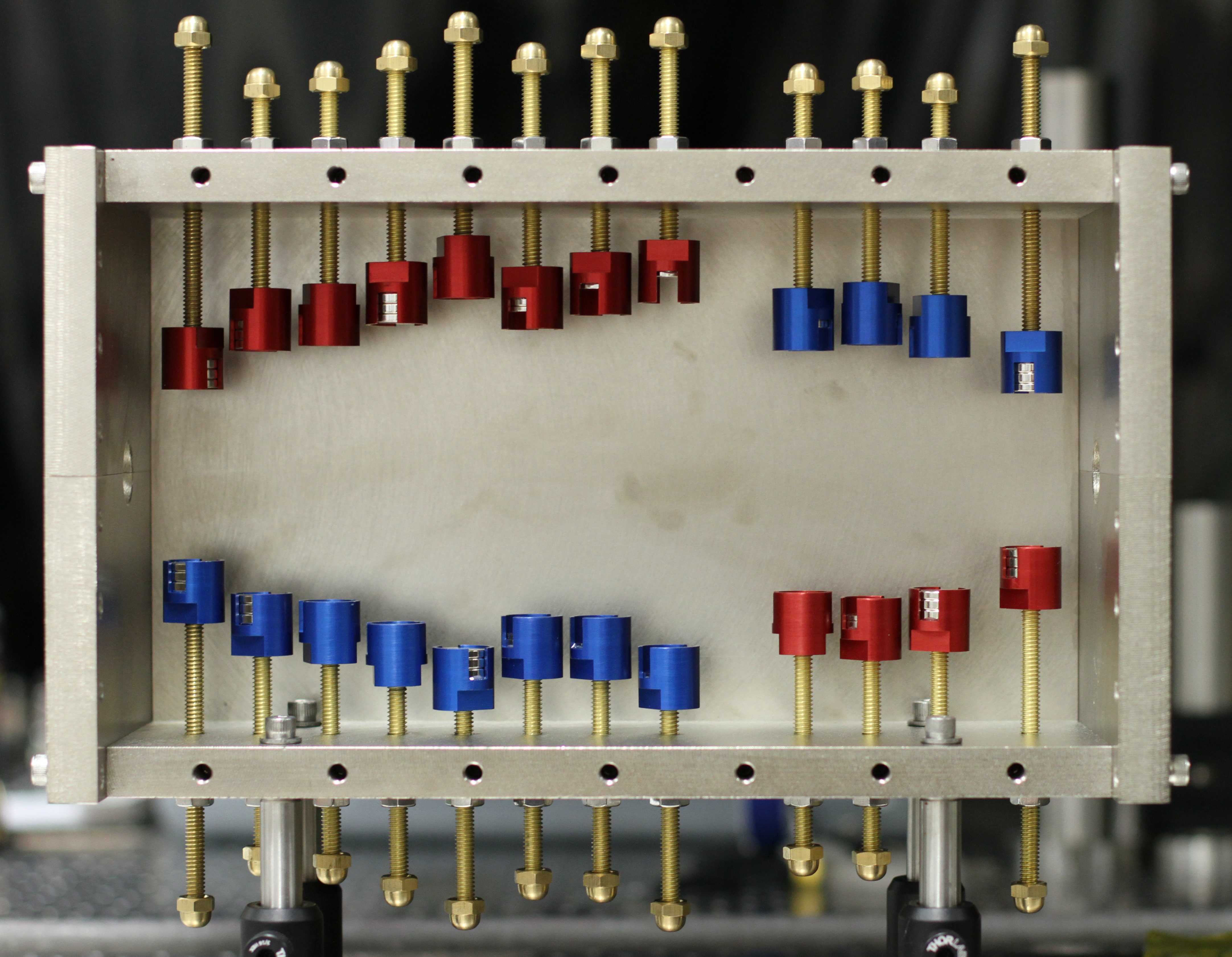
Zeeman Slower
The Zeeman slower is a device that utilizes relativistic and quantum effects to cool an atomic beam. To slow an atom that is traveling several hundred meters per second, we utilize photon absorption/spontaneous emission cycling which results in a net change in momentum in the direction of laser beam propagation. For this to work, the laser must be tuned to the proper atomic transition. Slowing an atom has the inevitable side effect of changing the wavelength that the atom "sees" due to the Doppler Shift. As the atom slows, the laser is no longer on resonance with the atomic transition. It is not practical to change the wavelength of the laser to correct this. To compensate for this effect, we exploit the Zeeman effect by using a position varying magnetic field which splits the atomic transition into several distinct energy levels, some of which depend on the applied magnetic field. By applying the proper (constant) wavelength of laser light and magnetic field profile, we compensate for Doppler Shift and slow a large fraction of the atomic beam to a temperature of several Kelvin.
The magnetic dipoles and their mirror images in the slower housing were modeled in Mathematica. The positions and stregths of these dipoles were taken from the Ovchinnikov paper, available on the projects site. The resulting field profile was matched in the actual Zeeman Slower. All attachments are finallized and the slower awaits application.
The animation below shows a height varying cross section of a top-down view of the magnitude of the total magnetic field in the range B = [0,5] gauss (higher intensities are whited out) in increments of 0.5 gauss with the image dipoles on the lower side removed. The protrusion of the field at the bottom shows that removal of the sidewall during operation would result in significant stray field escaping the housing.
I have worked on several science projects outside of the lab.